What Should I Pay Attention to When Using Mud Motors in HDD Drilling?
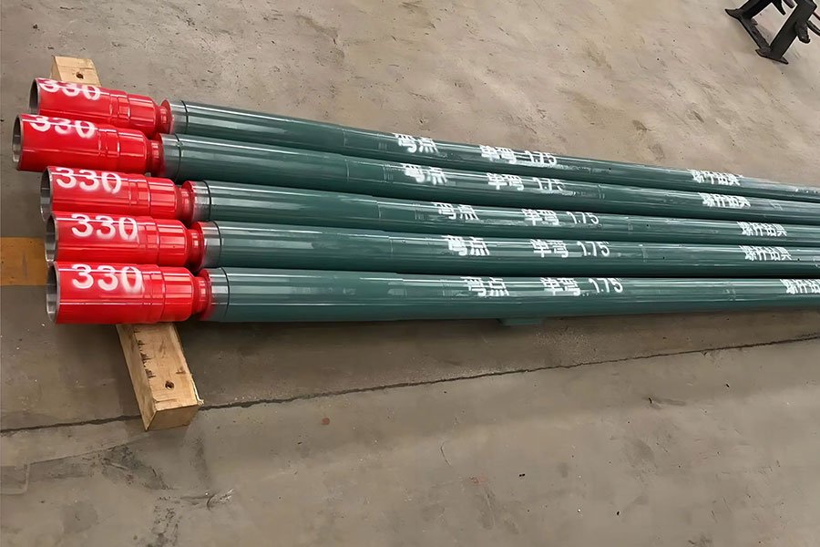
As the core power component of horizontal directional drilling, the mud motor (also known as a downhole mud motor) directly determines the ability to precisely control the drilling trajectory, drilling efficiency, and the success of the entire project. Compared to surface drilling rigs, which directly rotate the drill pipe, a mud motor utilizes high-pressure mud to drive an internal rotor, enabling the drill bit to rotate independently at the bottom of the hole. This makes it an indispensable tool for directional drilling. However, its sophisticated structure and operating principle also require strict operating procedures during use, otherwise it can easily cause equipment damage or operation failure. This article will focus on key issues that require special attention when using a mud motor for HDD drilling.
Strictly Prevent “Sand Plugging” And Ensure Mud Cleanliness And Operation Order
Mud motors consist of a precise stator-rotor assembly, requiring extremely high mud cleanliness. Sand blockage is a fatal problem for mud motors. Once it occurs, it can cause the motor to jam and shut down, or even tear the rubber bushings in the motor stator and wear out the rotor, rendering it useless.
Core measures:
Mud purification is crucial:
Slurry containing sand, rock debris, or other hard debris is strictly prohibited, especially recycled mud (unless it has been rigorously filtered and purified). These particles can enter the narrow gaps inside the motor with the mud, quickly accumulating and blocking the rotor or scratching the stator rubber. Always use fresh, high-quality mud that has been thoroughly stirred and filtered (e.g., through a vibrating screen, desander, or desilter) to ensure good lubricity and rock-carrying capacity.
Eliminate air injection into drill pipe:
Injecting air into the drill pipe disrupts the continuity of the mud column. When the pump is stopped or pressure fluctuates, negative pressure can easily form within the drill pipe, causing mud in the hole, or even dirty mud containing cuttings, to be sucked back into the motor, causing instantaneous blockage and severe wear. Ensure that the mud circulation system is properly sealed.
The correct order of operations is an iron rule:
During startup, the principle is: “Grout first, then drill .” Before starting the drill rig to rotate or propel, the mud pump must be started to establish stable mud circulation and pressure, ensuring that the motor is filled with clean mud and begins to rotate. Otherwise, a dry start or a low-flow start can instantly damage the stator rubber.
When stopping drilling: “Stop the drill rig first, then the pump .” When stopping drilling (for example, to connect drill pipe or take measurements), first stop the rotation and thrust of the drill rig. Keep the mud pump running for a while (usually 30 seconds to 1 minute) to allow the mud to continue flushing the motor and drill bit, removing any remaining rock debris and cooling the motor. Finally, stop the pump. If you stop the pump first, the drill bit may become stuck in the rock formation, and any remaining rock debris may accumulate in the motor, potentially causing a jam or difficulty starting the next time.
Be Wary Of Motor “Pressure Holding” And Understand The Relationship Between Pressure And Flow
The working principle of the mud motor determines that its speed is proportional to the mud flow rate , but not directly linearly related to the mud pressure . The pressure is the result of overcoming the system resistance (rock breaking by the drill bit, mud circulation resistance, friction, etc.).
Normal pressure range:
Under normal operating conditions (the drill bit is in contact with the formation and effectively breaking it), the pressure drop generated by the mud motor is typically in the range of 0-5 MPa (the specific value depends on the motor model and the drill bit load). This pressure is a reflection of the effective operation of the drill bit.
The essence of “holding pressure”:
When the mud pump’s flow rate is insufficient , the motor rotor receives insufficient driving force, resulting in a low or even intermittent rotational speed (“creep”) . At this point, if the drill bit is heavily loaded (such as in hard formations), the drill attempts to advance, but the motor’s low rotational speed is unable to effectively break the rock. This causes the system pressure to rise sharply, far exceeding the normal range (>5 MPa). This is known as “pressure holding.”
The dangers of “holding pressure”:
Extremely high pressure can cause excessive extrusion and heat accumulation on the motor stator rubber, accelerating rubber aging, deformation, and even tearing.
The mud pump, high-pressure pipelines and joints may be damaged.
This leads to an increased risk of torsional deformation or even breakage of the drill pipe.
Drilling efficiency drops sharply or even stagnates.
How to avoid holding back pressure ?
The key is ensuring adequate mud pumping capacity . Operators should set and maintain adequate pumping capacity based on the recommended flow range of the selected mud motor (consult the manufacturer’s manual) and formation conditions. If pump pressure rises abnormally (exceeding the normal WOB range or the motor’s maximum pressure), the first action is to immediately reduce WOB (pull back or stop thrust) and check for adequacy of pumping capacity , rather than blindly increasing pressure. Monitoring motor speed (if a sensor is available) is a direct way to determine whether flow is adequate.
Maintain Appropriate Motor Speed To Ensure Efficient And Stable Drilling
The efficiency and service life of a mud motor are closely related to its rotational speed.
Minimum speed requirement:
During construction, the normal speed of the mud motor should be maintained above 80 RPM . This is the critical threshold to ensure stable motor output torque and avoid “creeping” and pressure buildup.
The dangers of too low speed:
- Directly lead to pressure buildup: As mentioned above, when the rotation speed is insufficient, it cannot effectively overcome the drill load and the pressure will increase abnormally.
- Low drilling efficiency: Low rotation speed means that the drill bit breaks the rock less frequently and the drilling speed is slow.
- Unstable torque output: The “creep” phenomenon will generate impact loads, which are detrimental to the motor itself, drill rod and drill bit.
- Abnormal wear of stator rubber: At low speeds, the friction between the rotor and stator rubber is poor, which may aggravate wear.
Determinants of speed:
The speed of a mud motor is determined solely by the mud flow rate through the motor (within the rated operating differential pressure). The greater the flow rate, the higher the speed (a directly proportional relationship). Pump pressure reflects system resistance and is not a variable that controls speed. Operators must control motor speed by adjusting the mud pump’s displacement (stroke rate), rather than attempting to control speed by adjusting pressure. Always refer to the flow-speed curve provided by the motor manufacturer.
Understand The Mechanism Of Steering Angle Changes To Cope With Challenges In Soft Rock Formations
The core of mud motor steering lies in its fixed steering bend ( Bent Housing ) . This is fundamentally different from the principle of conventional steering drill bits that rely on the interaction between the drill bit face and the formation to generate lateral force.
Fixed bend principle:
The mud motor body (housing) is machined with a fixed, slight bend angle near the drill bit ( a common standard angle is 1.75° ). When the entire drill string is not rotating (only the motor drives the drill bit) for steerable drilling, the drill bit’s direction of travel is determined by this fixed bend point. The maximum theoretical angle the drill string can achieve at the deflection point is the motor’s fixed bend angle ( 1.75°) . For each unit length of drill string advanced, the trajectory direction changes by approximately this angle (actually affected by the formation).
Special challenges of soft rock formations:
In very soft or plastic rock formations (such as some mudstones and weathered rocks), the drill bit in front of the fixed bend (at 6 o’clock) cannot generate sufficient lateral support force (the formation is too soft to effectively “support” the bend). This will result in the actual deflection effect.
It is far below the theoretical bending angle (possibly less than 1°), or even completely unable to deflect in the predetermined direction.
Countermeasures – Wear Pad / Knuckle Buster :
Working principle:
A hard flat plate (resistance-enhancing plate) is welded to the housing in front of the motor bend (at 6 o’clock, i.e., pointing in the predetermined deflection direction) . This plate increases the contact area between that side and the hole wall.
Effect:
the frictional resistance generated by the friction plate and the soft rock formation increases . This resistance “opposes” the straight-line forward movement of the drill string, forcing the bend point effect to be amplified, effectively increasing the actual deflection angle , bringing it closer to or even reaching the theoretical bend angle value of the motor.
Notes:
- The welding must be firm and reliable to avoid falling off and becoming debris underground.
- The resistance plate will increase the outer diameter of the drill tool, and the drilling diameter limitation must be considered.
- In hard formations, the drag plate may cause excessive wear or the risk of drill sticking and should be used with caution.
Conclusion : Standardized operation is the cornerstone of success and efficiency
The mud motor, the heart of HDD directional drilling, ensures efficient and stable operation, crucial for project precision, efficiency, and cost control. Strictly controlling mud cleanliness and adhering to the ironclad principle of “grouting before drilling, and stopping drilling before stopping the pump” can minimize fatal sand jams. A deep understanding of the relationship between flow rate determining speed and pressure reflecting load , and ensuring a speed above 80 RPM , is crucial for avoiding pressure buildup and ensuring efficient drilling. Mastering the principle of fixed-point steering and its limitations in soft rock formations , along with the appropriate use of auxiliary tools such as drag plates , allows for precise control of the drilling trajectory.
In short, using a mud motor in HDD drilling is more than a simple “plug it in and go” approach. Instead, it requires operators to possess solid theoretical knowledge, a rigorous understanding of operating procedures, and the ability to flexibly address on-site challenges. Only by internalizing these precautions into standardized operating habits can the technical advantages of mud motors be fully utilized, reducing equipment failure rates, increasing construction success rates and economic benefits, and ensuring the safe, efficient, and precise completion of HDD projects. As the application of HDD technology becomes increasingly widespread and complex, the importance of standardized mud motor use must also continue to increase.
- Strictly Prevent "Sand Plugging" And Ensure Mud Cleanliness And Operation Order
- Be Wary Of Motor "Pressure Holding" And Understand The Relationship Between Pressure And Flow
- Maintain Appropriate Motor Speed To Ensure Efficient And Stable Drilling
- Understand The Mechanism Of Steering Angle Changes To Cope With Challenges In Soft Rock Formations
- Conclusion : Standardized operation is the cornerstone of success and efficiency
SHARE:
More Posts for You
- Navigating Underground Obstacles: The Precision Application of Drill Stem Steering Technology
- No More “Open Surgery” for Cities: The HDD Technologies Making It Possible
- The Heartbeat of HDD: A Deep Dive into the Mud Pump
- Barrel Reamers Plays An Important Role in Modern HDD Operations
- Your Drill Pipe Doesn’t Immediately Break When You Exceed Its Bend Radius
- All Terrain Drilling: The Smarter Way to Drill Through Rock
- How One-Piece Fluted Reamers Conquer Tough HDD Jobs
- Horizontal Directional Drilling Rig Operating Procedures
