HDD Drill Rod Selection for Engineers | Design and Analysis Fundamentals
Hey, engineering friends — let’s talk about drill rod selection.
I have been in the HDD drill rod world for 5 years now. I work in a drill rod factory. I get the same question asked a dozen different ways every week from contractors and engineers. ‘How do I pick the right drill rod for this job?’
And to be honest? I got it. A drill rod looks simple on paper. It’s a steel tube with threads on it. How difficult can it be, right?
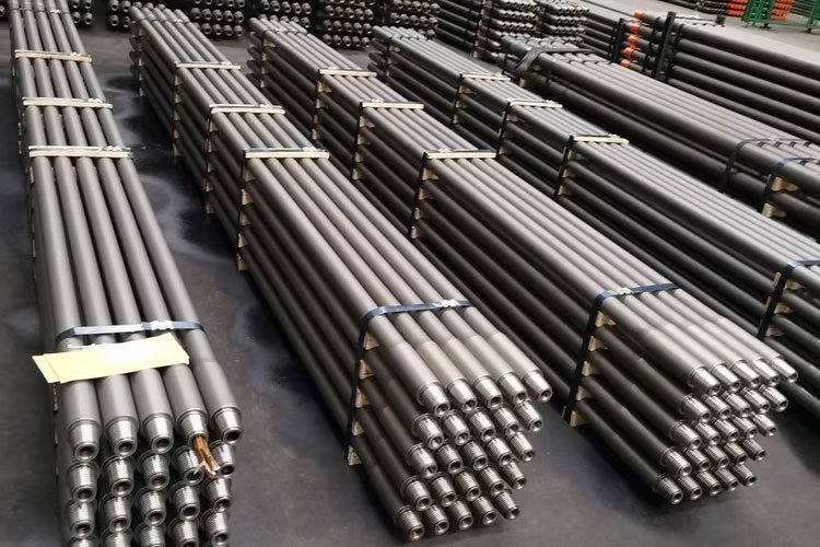
Then you get on the job site and the trajectory has a tight curve, the ground is mixed, the rig is working harder than you thought, and suddenly everybody is very interested in drill rod design and analysis. Funny how that works,
So this is my friendly, non-textbook, slightly opinionated guide to the basics of HDD drill rod selection for engineers. I won’t pretend this is a complete design manual. But if you’re a young engineer or a project engineer or even an experienced hand that wants a sanity check this should help.
First: the drill rod is not the weak link – the joint often is
Okay, here’s my first little rant.
People like to calculate the pipe body. OD, ID, yield strength, wall thickness—everyone has a spreadsheet for that.” And yes it is a count. But in HDD a lot of failure takes place at the joint. Thread roots, shoulders, make-up torque, wear, galling, fatigue. The drama is in the joint.
One customer told me, “We’re only at 60 percent of the tensile capacity of the rod, so we’re fine. “What’s your make-up torque, what’s your DLS through the curve, and who is watching the thread wear?” I asked. Quiet. Beautiful, beautiful quiet.
So when you choose a drill rod, please don’t just look at the body of the pipe. Think of the connection as a system . Thread form , shoulder contact , make-up torque , compatibility with the rig and wrench . A drill rod is not a commodity tube. It’s a precision connector that just happens to have a pipe attached.
The loads you really have to worry about
When I select HDD drill rod I usually divide the load picture into 4 buckets:
- Stress and prestressing force
This is the obvious one. You have the weight of the product, friction, drag, buoyancy, and the pullback force. The rod has to take it. Axial stress is tension divided by cross-sectional area, basically. Simple enough, until friction comes along to ruin your day. - Moment of force
Torque is what matters if you’re spinning. This torque results in shear stress in the rod . It also loads the joint . Don’t just look at torque capacity vs max torque of your rig and think you’re done. You have to think about real downhole torque. Friction, bit or reamer torque, hole condition, mud, how much you’re rotating in the curve. - Bending of trajectory
This is where HDD gets interesting. The rod goes through a bend. The sharper the curve, the more bending stress and fatigue you apply to the rod and joint. Engineers often use dogleg severity or DLS as a quick indicator . High DLS with rotation and tension is a bad mix. I have seen rods that were “fine” in straight sections go very unhappy in the curve. - Vibration and Buckling .
The rod can buckle when you push. In horizontal holes you can get sinusoidal or helical buckling depending on the load and the hole clearance. Vibration – torsional, axial, lateral – can also beat up threads and connections. This is where the spreadsheet gets nervous and the field guys say, “Yeah, it’s shaking a lot.” Both are saying something to you .
Combined stress: don’t look at one number in isolation
A common mistake is to check tension only . Then check torque only . Then check bending only . If each one passes , the rod is fine .
“Not the way it works, buddy.
In HDD the rod is often subjected to tension and torque and bending at the same time. So you need to do a stress test combined. You can use a Von Mises type approach or the manufacturers design method but the idea is simple. The loads add up. Compare the combined stress to the material yield strength with an appropriate factor of safety. Be aware of fatigue at the joint.
And please – this is my second little rant – don’t take a 2.0 safety factor and slap it on everything and call it engineering. Safety factors aren’t garlic. You can’t just add more and make the problem go away. You need to know which load case you are protecting against, whether it’s static overload, fatigue, make-up torque, wear or buckling. Different problems, different checks.”
A fast working workflow
When I assist a customer with drill rod selection review, I usually ask for five things:
Rig specs max pullback max torque rotation speed push capacity
Trajectory – planned DLS, radius of curvature, angle of entry, total length
Ground conditions – soil, rock, mixed face, abrasivity, stability.
Tooling and product – reamer size, product weight, swivel, buoyance plan.
Operating plan – rotation or no rotation, mud program, make-up torque expected.
Then we do some basic checks:
Tension and pull back load v rod capacity
Torque capacity vs. anticipated downhole torque
Bending and DLS versus recommended limits
Buckling possible in push parts
Joint makeup torque and compatibility
Considerations of fatigue and wear
Criteria for inspection and disposal
That last one is ignored a lot. Drill rods don’t last forever. They wear, they corrode, threads get damaged and hard banding wears out. A rod that passed design checks when it was new might not be the same rod after two years of rough jobs. Inspection is important. When you are designing for safety, design for the actual condition of the rod, not the brochure.
My little story field
A contractor called me several years ago, they were having thread failures on a mixed ground job. They’d selected rods based on rig pull back capacity and that sounded reasonable. But the curve of the trajectory was tighter than they had planned, they were rotating through it, and the crew was feeling out the joints. By touch. I love those guys. But no.
We crunched the numbers, looked at DLS and makeup torque, and went to a rod with a more appropriate joint and wall thickness for that curve and torque load. We also provided them with a make-up torque procedure and a simple routine for inspecting the threads. Failures ceased. It wasn’t magic. Nah. It was respect for the joint and basic design and analysis.
The thing is, most of the drill rod problems I see are not exotic. basics that were forgotten because everyone was in a hurry.
So what is the bottom line?
If you are an engineer selecting HDD drill rod, do not just buy the cheapest rod that will fit your rig. Think in terms of load cases: tension, torque, bending, buckling, fatigue. Make the joint part of the design. Use DLS and trajectory data. Check stress in joints. Do not over-torque. And plan for inspection and wear.
No need for a supercomputer for the first pass. You need a good picture of the load, and a manufacturer who will talk to you about the details. Send me your rig specs, trajectory, ground conditions and tooling plan and I’ll gladly nerd out with you. That’s basically my favorite part of the job – besides correcting people who call drill rods “just pipes.” Don’t do that, please. Just kidding. Mostly.
SHARE:
More Posts for You
- Developing a Smarter HDD Drill Rod Procurement Strategy: From Line Item to Performance Spec
- Which one lasts longer, one-piece forged drill rod or friction-welded drill rod?
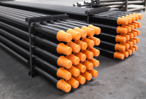
- HDD Drill Rod Selection for Engineers | Design and Analysis Fundamentals
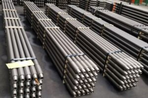
- Pre-Bore HDD Drill Rod Inspection Checklist: What to Check Before Every Job
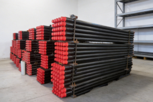
- HDD Drill Rod Warranty – What’s Covered and What Voids It

- Smart HDD Drill Rods: Sensors Embedded For Real-Time Monitoring
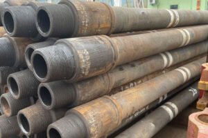
- Ultrasonic Wall Thickness Testing of HDD Drill Rods: Procedure & Limitations
- Choosing the right drill pipe supplier for your Vermeer D16x20