Ultrasonic Wall Thickness Testing of HDD Drill Rods: Procedure & Limitations
I have been in this industry on the drill rod side for five years now and I still get the same phone call at least once a month:
I put a UT gage on my HDD rod and got a weird number. “Is it rubbish?”
My answer is more often than not: “Maybe. But first tell me where you measured it.
That question has rescued many a perfectly good drill rod from the scrap bin. It’s why I stopped treating ultrasonic wall thickness testing as a magic answer box. UT is a great tool . But it’s a tool with a very specific job and if you use it wrong it will lie to you right to your face.
So let’s talk about what UT wall thickness testing really does, how I’d run it on HDD drill rods, and where it hits a wall.
What UT wall thickness testing really does
Ultrasonic thickness testing (or UT) is the sending of a high-frequency sound pulse into the steel. The pulse hits the far wall and bounces back, and the gage measures the time it took and the speed of sound through that steel to determine thickness.
That’s all. It ‘s essentially a very precise metal echo-location device.
It won’t tell you that the rod is cracked. Does not inform if the threads are cooked. It does not tell you the residual fatigue life. It tells you one thing. How thick the steel is at the very spot beneath the probe.
Sounds easy enough. It is not. That’s why HDD drill rods are not simple.
My First Big Epiphany at UT
About a few years ago a contractor called me up, almost in a panic. He had measured one of his HDD rods and had gotten a reading of about 9.2 mm. The nominal body wall was . . . 7.1 mm . . .” He figured the gage was broken, or the rod was some weird out of spec mess.
‘Where do you measure?’ I asked him.
“Just beside the tool joint.”
Ah. There’s the upset. The thickened transition zone. It is supposed to be thicker. The rod was good. He was taking a design characteristic and calling it a flaw.
That’s the first big lesson I learned. UT doesn’t know what you want to design. You have to know the stick.
How I would drill a rod in HDD for UT
I won’t pretend this is a formal procedure for every shop. Your OEM or inspection plan might be more stringent. But this is the practical version I would trust out in the field.
- Clean the area thoroughly
Mud, rust flakes, grease, paint, loose scale will all screw up the reading. Wire brush it, wipe it down, get to the bare metal. If you are measuring through thick coating or hardbanding, remember that the number may include that layer – or not, depending on the setup. Either way, don’t take a guess. - Select repeatable test points
This is the part that people miss, this is the thing that matters most.
Don’t just jam the probe in there. Make a grid. I like to look after a drill rod:
Few stations along the length of the main body
multiple clock positions around the circumference, e.g. at 12, 3, 6 and 9 o’clock
Areas that chafe, bend or see the most wear
Off the threads Hardbanding Upset transition Unless you know what your doing

The idea is to make apples to apples comparisons over time. Same places. Same orientation. Same method.
- Calibrate to a known reference
Use a calibration block – preferably similar material and thickness range. Set speed of sound. Zero the probe. If you have a generic steel block, but the rod is a different alloy or heat treat, you can get a little offset. It’s not usually big, but it’s real. - Use appropriate couplant
Air is not a conductor for ultrasonic sound. You need some sort of couplant, gel, glycerin, oil, water. I’ve seen guys use the drilling mud. Please, don’t. Mud is for drilling, not for sex. It produces noisy, unreliable readings and is a mess. - Keep the probe flat and steady
The probe should be at right angles to the surface. It takes a little practice on a curved stick. The reading increases when the probe is shaken. At each location, take multiple readings and use the minimum thickness, not the average. It’s the thin spot that matters. - Trend and log
One UT number is pretty much worth nothing. UT numbers from the same spots over months or years are priceless. “That’s how you see wall loss happening before it becomes a failure.”
Where UT hits a wall The boundaries
This is what makes me stay honest. UT is no miracle worker . Here is what it can’t do, or has problems with.
It’s a spot check, not a full scan
The probe can only see a small area below itself. If you have a deep pit the size of a pea two inches away, you can miss it entirely. That’s why you need a grid and a trend and not one random reading.
Surface condition counts – big time
Rough, pitted, scaly or coated surfaces can give false readings. A grinder can also clean a spot and grind away metal, making the wall look thinner than it actually was. I have seen that happen. Don’t be that person.
Geometry will fool you
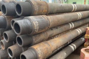
HDD drill rods have upset ends, tool joints, threads, hardbanding and sometimes wear pads . UT thickness gages are calibrated on flat parallel walls. Curved surfaces, internal upsets, and transitions can bend the sound beam or give you a thicker or thinner number that doesn’t mean what you think it means.
It will not find cracks or damage to threads.
Wall thickness is not crack detection A rod may have perfect wall thickness and still be unsafe due to a transverse crack, damaged thread, or bent tube. UT thickness testing is not a substitute for visual inspection, thread gages, MPI or other NDT methods.
Sound speed depends on the material and temperature
Different steels have different sound velocities. The reading can also be affected by high temperatures. If you’re testing right after a hot job, let it cool or use the proper compensation.
Operator Skill Massive
Whenever a good tech with a cheap gage beats a bad tech with an expensive gage. Technique, couplant, calibration and knowing where to measure it all!
The Real Lesson
I used to think UT was a judgment, Now I use it as a compass.
It points you to what is happening. It helps you monitor wear. It can detect a problem before it becomes a breakdown. But it doesn’t replace knowledge of the rod, a proper inspection program and good record keeping.
If you’re testing HDD drill rods, don’t just ask “What’s the number?
Ask, “Where did you take the measurement, did you calibrate, and what was the last reading?”
That’s the talk that saves rods — and jobsites.
If you are unsure where to measure on your rods or what your OEM considers the minimum wall give us a call. I do this all day long and am happy to discuss it. Not a sales pitch. Just rod nerd stuff, drill.
SHARE:
More Posts for You
- Developing a Smarter HDD Drill Rod Procurement Strategy: From Line Item to Performance Spec
- Which one lasts longer, one-piece forged drill rod or friction-welded drill rod?
- HDD Drill Rod Selection for Engineers | Design and Analysis Fundamentals
- Pre-Bore HDD Drill Rod Inspection Checklist: What to Check Before Every Job
- HDD Drill Rod Warranty – What’s Covered and What Voids It
- Smart HDD Drill Rods: Sensors Embedded For Real-Time Monitoring
- Ultrasonic Wall Thickness Testing of HDD Drill Rods: Procedure & Limitations
- Choosing the right drill pipe supplier for your Vermeer D16x20